One pod
40 m² collector, 0.80 m² rail. A house, not a business.
PR-B01 / PR-C01
Cheap mirrors in the dirt. A hot pipe they all point at. Tanks, turbines, and science experiments sit downstream — not on the focus. The field stays. Receivers evolve.
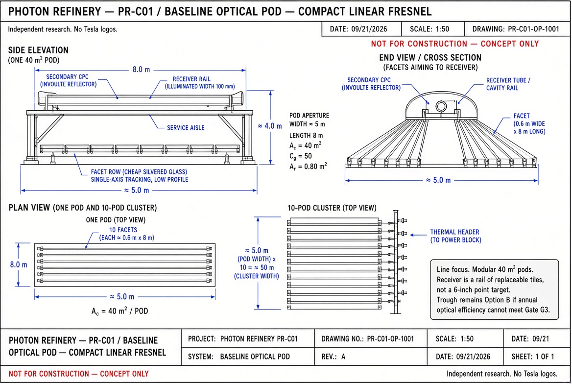
PR-C01 · Compact linear Fresnel · Cg = 50
Cg = Ac / Ar
Use effective illuminated receiver area, not the physical shell. For a 40 m² pod at 50× the receiver is 0.80 m². A 5,000 m² field at 50× needs about 100 m² of receiver, distributed across many tiles — never a 6–8 inch aperture.
Pin = DNI × Ac
Incident solar power on collector aperture.
Prec = Pin × ηopt
Optical efficiency includes reflectance, cosine, shading, intercept, and secondary losses.
Prad ≈ ε σ Aap T⁴
A cavity shrinks radiating area toward the aperture. It does not cancel T⁴.
ηth = Puse / Pin
System thermal efficiency after radiation, convection, and leak. Match temperature to the load.
No single point in the optical chain may rely on an unverified ultra-high concentration ratio.
Receiver area is derived from collector area and target concentration before dimensions are drawn.
Components not required at optical focus are moved downstream for cooling, service, and safety.
Each receiver generation must fit the same mechanical / thermal / electrical interface envelope.
40 m² collector, 0.80 m² rail. A house, not a business.
400 m² collector. Shared thermal header. One tile can fail without retiring the field.
120 pods, 4,800 m² collector, ~2.6 acres. Service aisle for cartridge swap.